
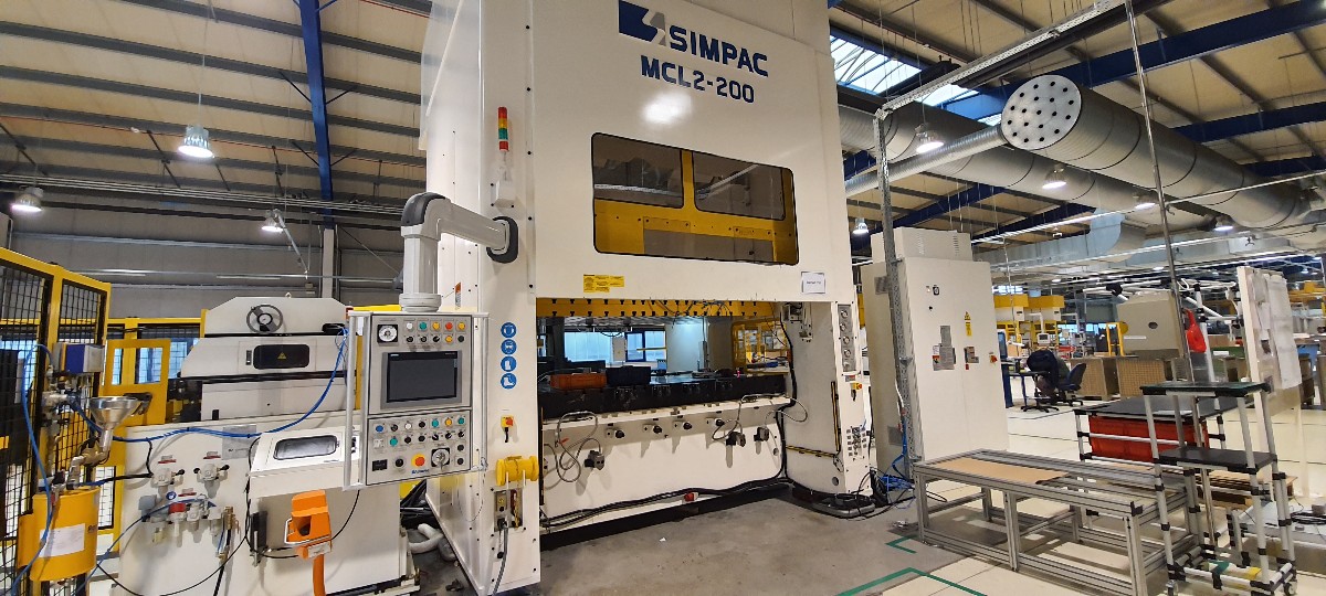
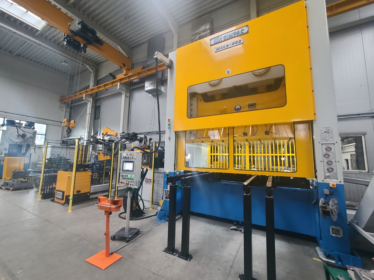
MC/MCL/MCP Series
Overview
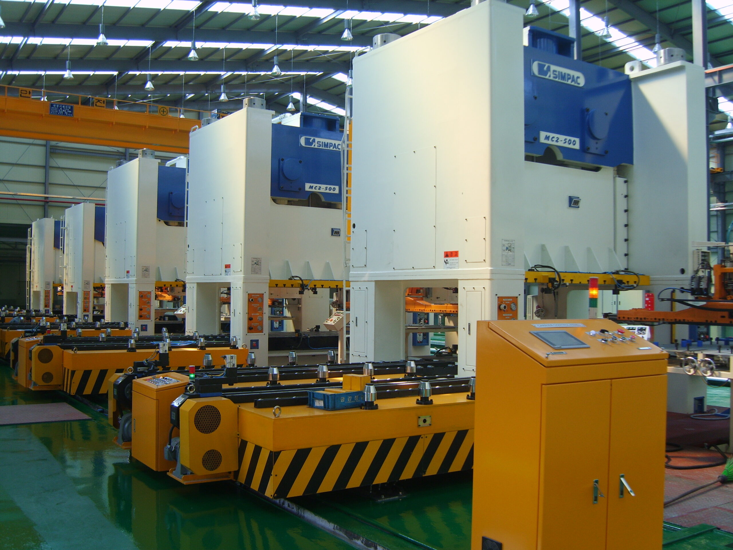
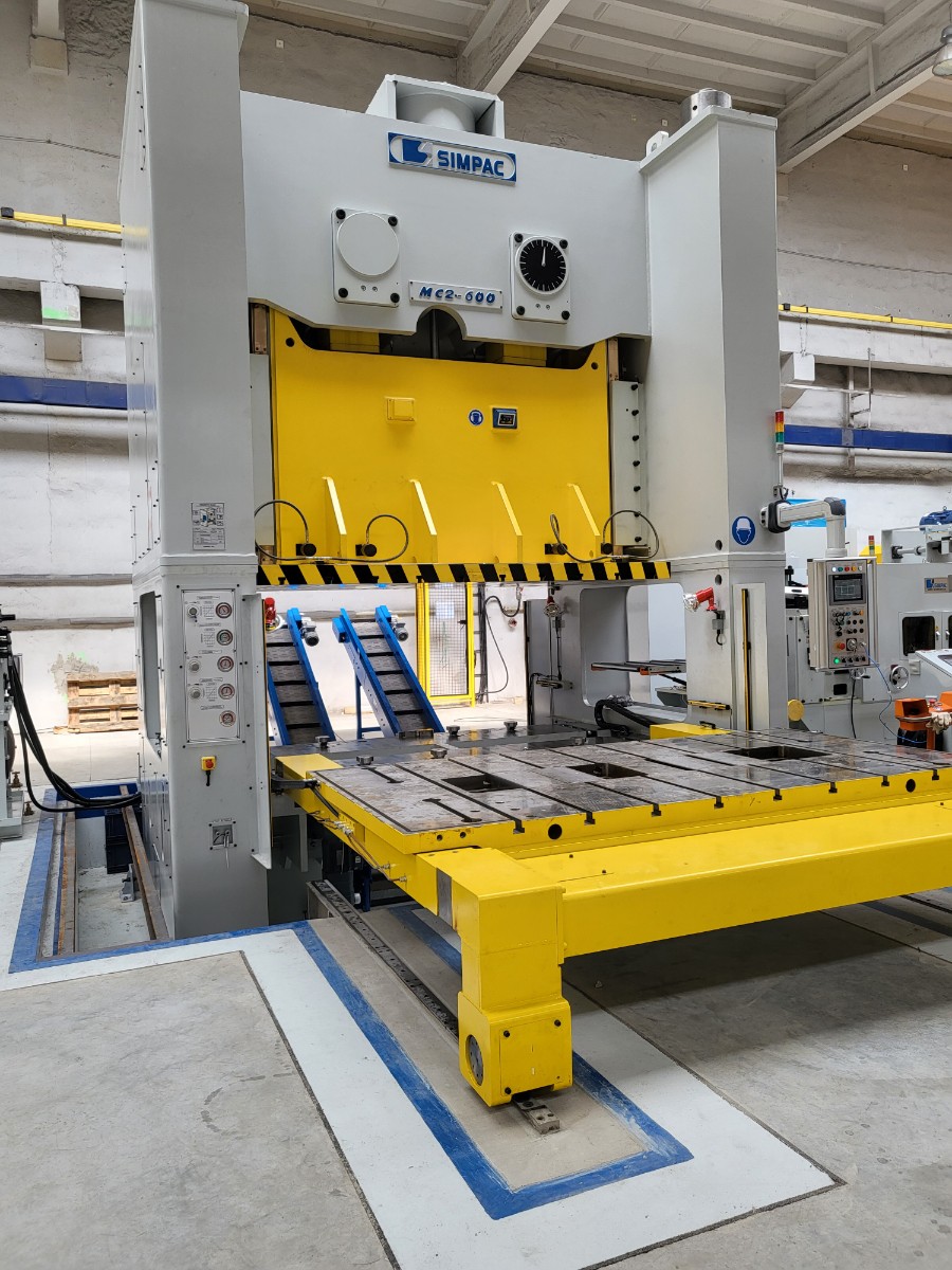
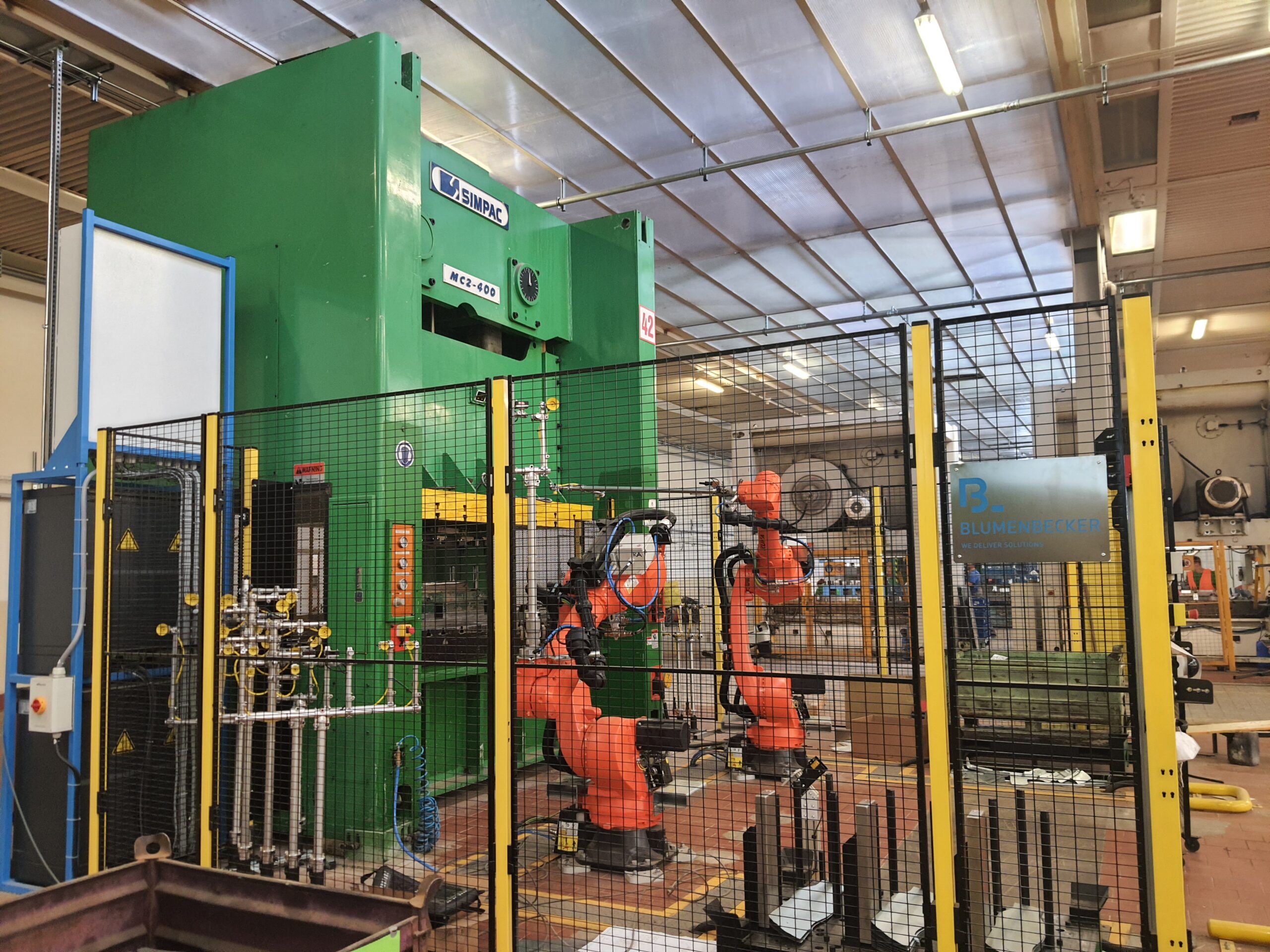
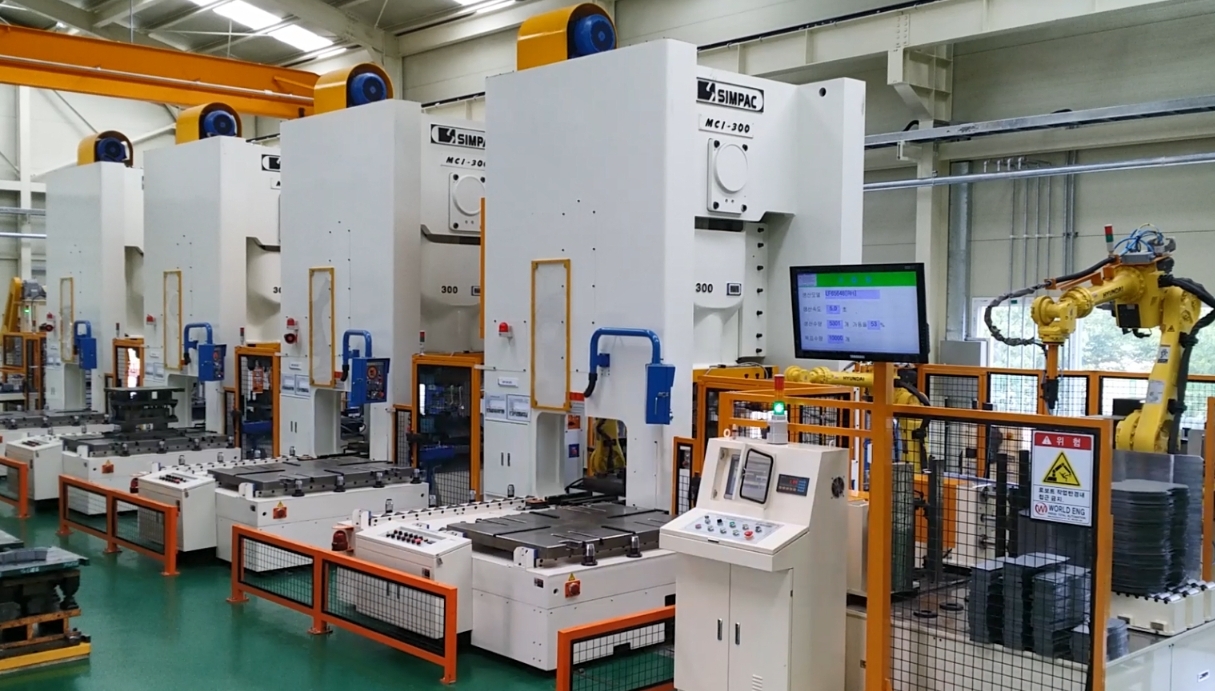
- Type: semi h-frame presses
- Press Capacity: 80-800 tons
- Part Size: small to medium
- Slide Kinematics: crank motion (MC; MCP) or link motion (MCL)
- Application: blanking, stamping, bending, embossing & drawing
Description
These compact presses are optimized for a wide range of small- to medium-sized parts. Due to the drive-related slide kinematics, the MCL Series, in particular, is ideal for drawn parts. The reduced forming speed increases the part quality and protects the press and dies.
Features & Benefits
- Flexible installation options as a single press in progressive or transfer mode or as a fully automated press line.
- The compact design requires little floorspace and no foundation for presses below 600 tons.
- The very solid, low-stress annealed press bodies are FEM-calculated and optimized by “hot-spot analysis” areas subject to higher loads.
- Motor, clutch/brake unit, lubrication system, and controls are of Korean origin and guarantee a long service life, maximum dynamics, and a supply of spare parts.
- When it comes to higher-strength materials, the slide guiding system ensures a high level of tilting rigidity and reduces the cutting impact during the cut through process.
Technical Specifications
- Metric
MC1 Series
| Model | MC1-110 | MC1-150 | MC1-200 | MC1-250 | MC1-300 | MC1-400 | MC1-500 | |
|---|---|---|---|---|---|---|---|---|
|
Press Capacity |
ton |
110 |
150 |
200 |
250 |
300 |
400 |
500 |
|
Rated Tonnage Point |
mm |
6 |
6 |
6 |
6 |
7 |
7 |
7 |
|
Stroke Rate
|
spm |
50-100 |
45-90
|
35-70
|
35-60
|
20-40
|
20-35
|
20-35
|
|
Stroke Length
|
mm |
110 |
130 |
160
|
200
|
250
|
280
|
350
|
|
Slide Adjustment |
mm |
100 |
100 |
120 |
120 |
120 |
120 |
120 |
|
Die Height |
mm |
350 |
400 |
450
|
500 |
500 |
550 |
600 |
|
Slide Dimension |
mm |
900x550 |
1000x650 |
1150x750 |
1250x750
|
1500x900
|
1650x1000
|
1800x1100
|
|
Bolster Dimension
|
mm |
1000x700
|
1150x750
|
1300x850
|
1400x950 |
1600x1000
|
1800x1100
|
1950x1200 |
|
Overall Height |
mm |
3100 |
3300 |
3705 |
4020 |
4575 |
4730 |
5650 |
|
Die Cushion Capacity |
ton |
10 |
14 |
14 |
14 |
14 |
14 |
15 |
|
Die Cushion Stroke |
mm |
80 |
100 |
100 |
100 |
130 |
130 |
130 |
|
Die Cushion Pad Area |
mm |
540x340 |
640x420 |
640x420 |
640x420 |
860x460 |
860x460 |
860x460 |
* SDAU = slide stroke down, adjustment up | ST = standard | HS = high-speed | LS = long stroke | Subject to technical modifications
MC2 Series
| Model | MC2-200 | MC2-250 | MC2-300 | MC2-350 | MC2-400 | MC2-500 | MC2-600 | MC2-800 | |
|---|---|---|---|---|---|---|---|---|---|
|
Press Capacity |
ton |
200 |
250
|
300 |
350
|
400 |
500 |
600 |
800 |
|
Rated Tonnage Point
|
mm
|
7 |
7 |
6 |
6 |
7 |
7 |
7 |
7 |
|
Stroke Rate |
spm |
25-80 |
25-80 |
25-80 |
15-70 |
15-70 |
15-60 |
15-60 |
15-50 |
|
Stroke Length |
mm |
250 |
280 |
300 |
300 |
350 |
350 |
350 |
350 |
|
Slide Adjustment |
mm |
110 |
120 |
120 |
120 |
120 |
120 |
120 |
120 |
|
Die Height |
mm |
500 |
550 |
550 |
600 |
600 |
650 |
700 |
700 |
|
Slide Dimension |
mm |
1850x650 |
2400x1000
|
2600x1000
|
2600x1200 |
2700x1300 |
3000x1300 |
3000x1400
|
3200x1400 |
|
Bolster Dimension |
mm |
2150x850 |
2500x1100 |
2700x1100 |
2700x1200 |
2800x1400 |
3000x1400 |
3000x1500 |
3200x1500 |
|
Overall Height
|
mm |
3775
|
4390 |
4545
|
4595 |
5105 |
5500 |
5860 |
6300 |
|
Die Cushion Capacity |
ton |
22 |
22 |
22 |
22 |
30 |
30 |
30 |
30 |
|
Die Cushion Stroke |
mm |
100 |
110 |
110 |
110 |
140
|
140
|
140
|
140
|
|
Die Cushion Pad Area
|
mm
|
1000x400
|
1590x500
|
1590x500
|
1590x500
|
1750x500
|
1750x500
|
1750x500
|
1750x500
|
* SDAU = slide stroke down, adjustment up | ST = standard | HS = high-speed | LS = long stroke | Subject to technical modifications
MCP2 Series
| Model | MCP2-400 | MCP2-600 | MCP2-800 | |
|---|---|---|---|---|
|
Press Capacity |
ton
|
400
|
600
|
800 |
|
Rated Tonnage Point
|
mm |
6 |
6 |
6 |
|
Stroke Rate |
spm |
30-70 |
25-60 |
20-50 |
|
Stroke Length |
mm |
300 |
350 |
350 |
|
Slide Adjustment |
mm |
200 |
250 |
250 |
|
Die Height * |
mm |
600 |
800 |
800 |
|
Slide Dimension |
mm |
3000x1400 |
4000x1500 |
4000x1500 |
|
Bolster Dimension |
mm |
3000x1400 |
4000x1500 |
4000x1500 |
|
Main Motor (AC) |
kW |
75 |
90 |
90 |
|
Counterbalancing Capacity |
ton (MPa) |
5 (0.7) |
7 (0.7) |
7 (0.7) |
|
Frame Combined
|
|
Monobloc |
Tie Rod |
Tie Rod |
|
Frame Deflection |
mm/m |
1/8000 |
1/8000 |
1/8000 |
|
Anti-vibration Device |
|
Spring & Damper |
Spring & Damper |
Spring & Damper |
|
Pit |
|
Necessary |
Necessary |
Necessary |
* SDAU = slide stroke down, adjustment up | ST = standard | HS = high-speed | LS = long stroke | Subject to technical modifications | ** The above specifications are based on the maximum specifications
MCL1 Series
| Model | MCL1-80 | MCL1-110 | MCL1-150 | MCL1-200 | MCL1-250 | MCL1-300 | MCL1-400 | MCL1-600 | |
|---|---|---|---|---|---|---|---|---|---|
|
Press Capacity |
ton
|
80
|
110 |
150 |
200 |
250 |
300 |
400 |
600 |
|
Rated Tonnage Point |
mm |
4 |
6 |
6 |
6 |
6 |
7 |
8 |
8 |
|
Stroke Rate |
spm |
55-110 |
50-100
|
40-85
|
35-70
|
35-60
|
20-40
|
20-40
|
15-50
|
|
Stroke Length
|
mm |
100 |
110 |
130 |
160 |
200 |
250 |
300 |
350 |
|
Slide Adjustment |
mm |
80 |
100 |
100 |
120 |
120 |
120 |
120 |
120 |
|
Die Height |
mm |
320 |
370 |
400 |
450 |
470 |
500 |
500 |
500 |
|
Slide Dimension |
mm |
750x500 |
900x550
|
1000x650
|
1150x750
|
1250x750
|
1500x900
|
1650x1000
|
1650x1000
|
|
Bolster Dimension |
mm |
900x600 |
1000x700
|
1150x750 |
1300x850
|
1400x950 |
1600x1000 |
1800x1100
|
1800x1100
|
|
Overall Height |
mm |
2250 |
2400 |
2750
|
3050 |
3100 |
3100 |
3100 |
3700 |
|
Die Cushion Capacity |
ton |
8 |
10 |
14 |
14 |
14 |
15 |
15 |
15 |
|
Die Cushion Stroke |
mm |
80 |
80 |
100 |
100 |
100 |
130 |
130 |
130 |
|
Die Cushion Pad Area
|
mm |
480x300 |
540x340 |
640x420 |
640x420 |
640x420 |
640x420 |
860x460 |
860x460 |
* SDAU = slide stroke down, adjustment up | ST = standard | HS = high-speed | LS = long stroke | Subject to technical modifications
MCL2 Series
| Model | MCL2-200 (ST | HS) | MCL2-250 (ST | HS) | MCL2-300 | MCL2-400 | MCL2-500 | MCL2-600 | MCL2-800 | |
|---|---|---|---|---|---|---|---|---|
|
Press Capacity |
ton |
200 |
250
|
300
|
400
|
500
|
600
|
800
|
|
Rated Tonnage Point
|
mm
|
4 | 7 |
4 | 7 |
6 |
7 |
7 |
7 |
7 |
|
Stroke Rate
|
spm
|
35-70 | 25-45
|
30-55 | 20-40
|
20-40
|
20-40
|
20-30
|
15-50 |
15-40 |
|
Stroke Length |
mm |
150 | 250 |
170 | 250 |
250 |
300 |
350 |
350 |
350 |
|
Slide Adjustment |
mm |
120 |
120 |
120 |
120 |
120 |
120 |
120 |
|
Die Height |
mm |
450 | 500 |
450 | 500 |
600 |
700 |
700 |
700 |
700 |
|
Slide Dimension |
mm |
1850x650
|
2400x1000 |
2600x1000
|
2700x1300
|
2900x1300 |
3000x1400 |
3200x1400
|
|
Bolster Dimension |
mm |
2150x850
|
2500x1100
|
2700x1100
|
2800x1400
|
3000x1400 |
3000x1500 |
3000x1500 |
|
Overall Height |
mm |
3950 | 4210 |
4180 | 4390
|
4560 |
5120
|
5550
|
5910
|
6300 |
|
Die Cushion Capacity
|
ton
|
22 |
22 |
22 |
30 |
30 |
30 |
30 |
|
Die Cushion Stroke |
mm |
100 |
110 |
110 |
110 |
140 |
140 |
140 |
|
Die Cushion Pad Area
|
mm |
1000x400 |
1590x500 |
1590x500 |
1590x500 |
1750x500 |
1750x500 |
1750x500 |
* SDAU = slide stroke down, adjustment up | ST = standard | HS = high-speed | LS = long stroke | Subject to technical modifications | ** The above specifications are based on the maximum specifications